- 您现在的位置:买卖IC网 > Sheet目录509 > SI4420-D1-FT (Silicon Laboratories Inc)IC TXRX FSK 915MHZ 5.4V 16-TSSOP
Si4420
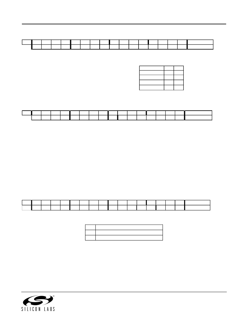
3. Frequency Setting Command
Bit
15
1
14
0
13
1
12
0
11
f11
10
f10
9
f9
8
f8
7
f7
6
f6
5
f5
4
f4
3
f3
2
f2
1
f1
0
f0
POR
A680h
The 12-bit parameter F (bits f11 to f0 ) should be in the range of
96 and 3903. When F value sent is out of range, the previous
The constants C1 and C2 are determined by
the selected band as:
value is kept. The synthesizer center frequency f 0 can be
calculated as:
f 0 = 10 * C1 * (C2 + F/4000) [MHz]
Band [MHz]
315
433
868
915
C1
1
1
2
3
C2
31
43
43
30
4. Data Rate Command
Bit
15
1
14
1
13
0
12
0
11
0
10
1
9
1
8
0
7
cs
6
r6
5
r5
4
r4
3
r3
2
r2
1
r1
0
r0
POR
C623h
The actual bit rate in transmit mode and the expected bit rate of the received data stream in receive mode is determined by the 7-bit
parameter R (bits r6 to r0 ) and bit cs .
BR = 10000 / 29 / (R+1) / (1+ cs *7) [kbps]
In the receiver set R according to the next function:
R= (10000 / 29 / (1+ cs *7) / BR) – 1, where BR is the expected bit rate in kbps.
Apart from setting custom values, the standard bit rates from 600 bps to 115.2 kbps can be approximated with small error.
Data rate accuracy requirements:
Clock recovery in slow mode: ? BR / BR < 1 / (29*N bit )
Clock recovery in fast mode: ? BR / BR < 3 / (29*N bit )
BR is the bit rate set in the receiver and ? BR is the bit rate difference between the transmitter and the receiver. N bit is the maximal number of
consecutive ones or zeros in the data stream. It is recommended for long data packets to include enough 1/0 and 0/1 transitions, and be
careful to use the same division ratio in the receiver and in the transmitter.
5. Power Setting Command
Bit
15
1
14
0
13
0
12
1
11
0
10
p16
9
d1
8
d0
7
i2
6
i1
5
i0
4
g1
3
g0
2
r2
1
r1
0
r0
POR
9080h
Bit 10 (p16) : pin16 function select
p16
0
1
Function of pin 16
Interrupt input
VDI output
14
发布紧急采购,3分钟左右您将得到回复。
相关PDF资料
SI4420DYTR
MOSFET N-CH 30V 12.5A 8-SOIC
SI4421DY-T1-GE3
MOSFET P-CH D-S 20V 8-SOIC
SI4427BDY-T1-GE3
MOSFET P-CH 30V 9.7A 8SOIC
SI4430BDY-T1-GE3
MOSFET N-CH 30V 14A 8-SOIC
SI4431BDY-T1-GE3
MOSFET P-CH 30V 5.7A 8SOIC
SI4435DDY-T1-E3
MOSFET P-CH 30V 11.4A 8SOIC
SI4435DY
MOSFET P-CH 30V 8.8A 8-SOIC
SI4435DY
MOSFET P-CH 30V 8A 8-SOIC
相关代理商/技术参数
SI4420-D1-FTR
功能描述:射频发射器 Transceiver EZRadio RoHS:否 制造商:Micrel 类型:ASK Transmitter 封装 / 箱体:SOT-23-6 工作频率:300 MHz to 450 MHz 封装:Reel
SI4420DY
功能描述:MOSFET 30V 400a N-Ch MOSFET RoHS:否 制造商:STMicroelectronics 晶体管极性:N-Channel 汲极/源极击穿电压:650 V 闸/源击穿电压:25 V 漏极连续电流:130 A 电阻汲极/源极 RDS(导通):0.014 Ohms 配置:Single 最大工作温度: 安装风格:Through Hole 封装 / 箱体:Max247 封装:Tube
SI4420DY,518
功能描述:MOSFET TRENCH<=30 RoHS:否 制造商:STMicroelectronics 晶体管极性:N-Channel 汲极/源极击穿电压:650 V 闸/源击穿电压:25 V 漏极连续电流:130 A 电阻汲极/源极 RDS(导通):0.014 Ohms 配置:Single 最大工作温度: 安装风格:Through Hole 封装 / 箱体:Max247 封装:Tube
SI4420DY
制造商:Vishay Siliconix 功能描述:MOSFET N SO-8
SI4420DY-E3
功能描述:MOSFET 30V 12.5A 2.5W RoHS:否 制造商:STMicroelectronics 晶体管极性:N-Channel 汲极/源极击穿电压:650 V 闸/源击穿电压:25 V 漏极连续电流:130 A 电阻汲极/源极 RDS(导通):0.014 Ohms 配置:Single 最大工作温度: 安装风格:Through Hole 封装 / 箱体:Max247 封装:Tube
SI4420DYHR
制造商:International Rectifier 功能描述:Trans MOSFET N-CH 30V 12.5A 8-Pin SOIC 制造商:International Rectifier 功能描述:TRANS MOSFET N-CH 30V 12.5A 8SOIC - Rail/Tube
SI4420DYPBF
功能描述:MOSFET 30V 1 N-CH HEXFET 9mOhms 52nC RoHS:否 制造商:STMicroelectronics 晶体管极性:N-Channel 汲极/源极击穿电压:650 V 闸/源击穿电压:25 V 漏极连续电流:130 A 电阻汲极/源极 RDS(导通):0.014 Ohms 配置:Single 最大工作温度: 安装风格:Through Hole 封装 / 箱体:Max247 封装:Tube
SI4420DYPBF
制造商:International Rectifier 功能描述:TRANSISTOR 制造商:International Rectifier 功能描述:N CHANNEL MOSFET, 30V, 12.5A, SOIC
